

This is part two of the ARM Assembly Basics tutorial series, covering data types and registers.

Similar to high level languages, ARM supports operations on different datatypes.
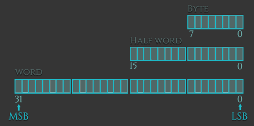
The data types we can load (or store) can be signed and unsigned words, halfwords, or bytes. The extensions for these data types are: -h or -sh for halfwords, -b or -sb for bytes, and no extension for words. The difference between signed and unsigned data types is:
Here are some examples of how these data types can be used with the instructions Load and Store:
ldr = Load Word ldrh = Load unsigned Half Word ldrsh = Load signed Half Word ldrb = Load unsigned Byte ldrsb = Load signed Bytes str = Store Word strh = Store unsigned Half Word strsh = Store signed Half Word strb = Store unsigned Byte strsb = Store signed ByteEndianness
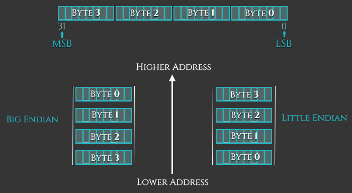
There are two basic ways of viewing bytes in memory: Little-Endian (LE) or Big-Endian (BE). The difference is the byte-order in which each byte of an object is stored in memory. On little-endian machines like Intel x86, the least-significant-byte is stored at the lowest address (the address closest to zero). On big-endian machines the most-significant-byte is stored at the lowest address. The ARM architecture was little-endian before version 3, since then it is bi-endian, which means that it features a setting which allows for switchable endianness. On ARMv6 for example, instructions are fixed little-endian and data accesses can be either little-endian or big-endian as controlled by bit 9, the E bit, of the Program Status Register (CPSR).

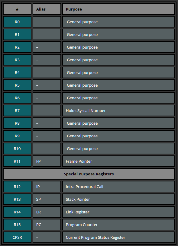
The amount of registers depends on the ARM version. According to the ARM Reference Manual, there are 30 general-purpose 32-bit registers, with the exception of ARMv6-M and ARMv7-M based processors. The first 16 registers are accessible in user-level mode, the additional registers are available in privileged software execution (with the exception of ARMv6-M and ARMv7-M). In this tutorial series we will work with the registers that are accessible in any privilege mode: r0-15. These 16 registers can be split into two groups: general purpose and special purpose registers.

| # | Alias | Purpose |
|---|---|---|
| R0 | – | General purpose |
| R1 | – | General purpose |
| R2 | – | General purpose |
| R3 | – | General purpose |
| R4 | – | General purpose |
| R5 | – | General purpose |
| R6 | – | General purpose |
| R7 | – | Holds Syscall Number |
| R8 | – | General purpose |
| R9 | – | General purpose |
| R10 | – | General purpose |
| R11 | FP | Frame Pointer |
| Special Purpose Registers | ||
| R12 | IP | Intra Procedural Call |
| R13 | SP | Stack Pointer |
| R14 | LR | Link Register |
| R15 | PC | Program Counter |
| CPSR | – | Current Program Status Register |
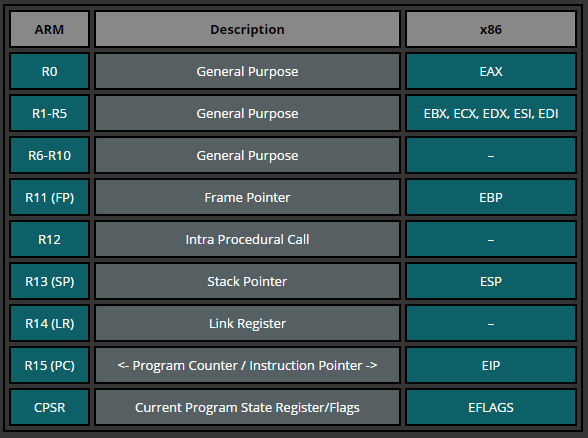
The following table is just a quick glimpse into how the ARM registers could relate to those in Intel processors.

| ARM | Description | x86 |
|---|---|---|
| R0 | General Purpose | EAX |
| R1-R5 | General Purpose | EBX, ECX, EDX, ESI, EDI |
| R6-R10 | General Purpose | – |
| R11 (FP) | Frame Pointer | EBP |
| R12 | Intra Procedural Call | – |
| R13 (SP) | Stack Pointer | ESP |
| R14 (LR) | Link Register | – |
| R15 (PC) | EIP | |
| CPSR | Current Program State Register/Flags | EFLAGS |
R0-R12: can be used during common operations to store temporary values, pointers (locations to memory), etc. R0, for example, can be referred as accumulator during the arithmetic operations or for storing the result of a previously called function. R7 becomes useful while working with syscalls as it stores the syscall number and R11 helps us to keep track of boundaries on the stack serving as the frame pointer (will be covered later). Moreover, the function calling convention on ARM specifies that the first four arguments of a function are stored in the registers r0-r3.
R13: SP (Stack Pointer). The Stack Pointer points to the top of the stack. The stack is an area of memory used for function-specific storage, which is reclaimed when the function returns. The stack pointer is therefore used for allocating space on the stack, by subtracting the value (in bytes) we want to allocate from the stack pointer. In other words, if we want to allocate a 32 bit value, we subtract 4 from the stack pointer.
R14: LR (Link Register). When a function call is made, the Link Register gets updated with a memory address referencing the next instruction where the function was initiated from. Doing this allows the program return to the “parent” function that initiated the “child” function call after the “child” function is finished.
R15: PC (Program Counter). The Program Counter is automatically incremented by the size of the instruction executed. This size is always 4 bytes in ARM state and 2 bytes in THUMB mode. When a branch instruction is being executed, the PC holds the destination address. During execution, PC stores the address of the current instruction plus 8 (two ARM instructions) in ARM state, and the current instruction plus 4 (two Thumb instructions) in Thumb(v1) state. This is different from x86 where PC always points to the next instruction to be executed.
Let’s look at how PC behaves in a debugger. We use the following program to store the address of pc into r0 and include two random instructions. Let’s see what happens.
.section .text .global _start _start: mov r0, pc mov r1, #2 add r2, r1, r1 bkpt
In GDB we set a breakpoint at _start and run it:
gef> br _start Breakpoint 1 at 0x8054 gef> run
Here is a screenshot of the output we see first:
$r0 0x00000000 $r1 0x00000000 $r2 0x00000000 $r3 0x00000000 $r4 0x00000000 $r5 0x00000000 $r6 0x00000000 $r7 0x00000000 $r8 0x00000000 $r9 0x00000000 $r10 0x00000000 $r11 0x00000000 $r12 0x00000000 $sp 0xbefff7e0 $lr 0x00000000 $pc 0x00008054 $cpsr 0x00000010 0x8054 mov r0, pc 0x8058 mov r0, #2 0x805c add r1, r0, r0 0x8060 bkpt 0x0000 0x8064 andeq r1, r0, r1, asr #10 0x8068 cmnvs r5, r0, lsl #2 0x806c tsteq r0, r2, ror #18 0x8070 andeq r0, r0, r11 0x8074 tsteq r8, r6, lsl #6
We can see that PC holds the address (0x8054) of the next instruction (mov r0, pc) that will be executed. Now let’s execute the next instruction after which R0 should hold the address of PC (0x8054), right?
$r0 0x0000805c $r1 0x00000000 $r2 0x00000000 $r3 0x00000000 $r4 0x00000000 $r5 0x00000000 $r6 0x00000000 $r7 0x00000000 $r8 0x00000000 $r9 0x00000000 $r10 0x00000000 $r11 0x00000000 $r12 0x00000000 $sp 0xbefff7e0 $lr 0x00000000 $pc 0x00008058 $cpsr 0x00000010 0x8058 mov r0, #2 0x805c add r1, r0, r0 0x8060 bkpt 0x0000 0x8064 andeq r1, r0, r1, asr #10 0x8068 cmnvs r5, r0, lsl #2 0x806c tsteq r0, r2, ror #18 0x8070 andeq r0, r0, r11 0x8074 tsteq r8, r6, lsl #6 0x8078 adfcssp f0, f0, #4.0
…right? Wrong. Look at the address in R0. While we expected R0 to contain the previously read PC value (0x8054) it instead holds the value which is two instructions ahead of the PC we previously read (0x805c). From this example you can see that when we directly read PC it follows the definition that PC points to the next instruction; but when debugging, PC points two instructions ahead of the current PC value (0x8054 + 8 = 0x805C). This is because older ARM processors always fetched two instructions ahead of the currently executed instructions. The reason ARM retains this definition is to ensure compatibility with earlier processors.